Table of Contents (click to expand)
The heating of the charger occurs primarily as a byproduct of the power conversion process. A straightforward way to convert power is to rectify AC wall power to DC through a diode bridge. This is less than 5% efficient, which is totally impractical for phone use.
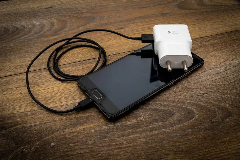
If you have a mobile device or a laptop, you obviously need to charge it regularly at frequent intervals. However, have you ever touched the charger during a charging cycle? Chances are, if you have, then you undoubtedly noticed that the charger dissipates a lot of heat, which is quite reasonable and nothing to be worried about. Before we get into the reason as to why the chargers heat up so much, we should provide a technical overview of the inner working of the chargers used for cell phones and laptops.
Recommended Video for you:
Switch Mode Power Supply (SMPS)
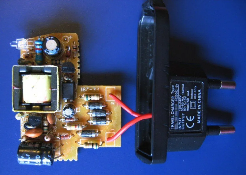
The chargers we use either for a mobile device or laptop are not ordinary wall plugs that provide a connection between the power supply unit and the device. This device is known as a Switch Mode Power Supply (SMPS), an electronic power supply that incorporates a switching regulator used in converting an electric power supply efficiently. SMPS are usually used to turn AC or DC power supply into DC loads (e.g., mobile phones and laptops), while changing the voltage and current characteristics. The way it does this is by continually switching between full on and full off states, hence the name Switch Mode Power Supply. Now, let’s look at the different stages to determine how the SMPS converts AC power into usable DC power for an electronic device.
Input Rectifier And Inverter Stage
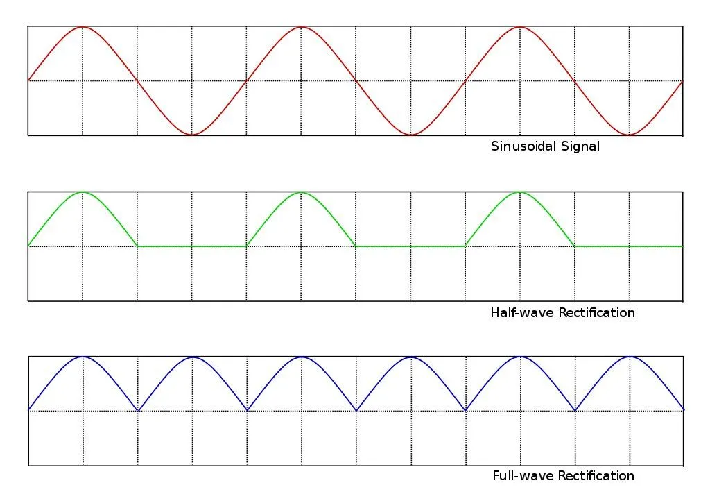
When the SMPS receives an AC input from the wall supply, the primary focus is to convert the input into DC. This process is known as rectification. The rectifier ends up giving an output that is in the form of unregulated DC voltage. This unrectified DC voltage is then sent to a capacitor. The current drawn from the main power supply by the rectifier circuit occurs in short pulses around the AC voltage peaks. An SMPS designed for an AC input can also run from a DC supply, as the DC would pass through the rectifier unchanged.
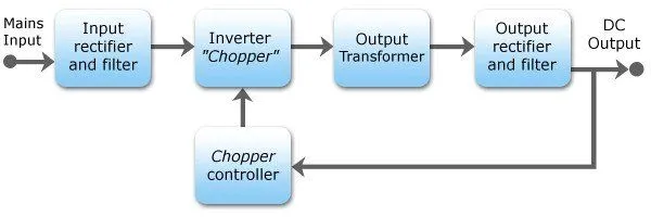
The inverter stage of the process involves the conversion of DC to AC either directly (if the source is a DC supply) or after the above mentioned rectifying stage is completed by running it through a power oscillator. The power oscillator consists of a small output transformer that has very few windings. These windings comprise a frequency of a few tens to hundreds of kilohertz. The frequency selected by default is primarily over 20 Khz. The constant switching action is performed by a MOSFET. The metal-oxide-semiconductor-field-effect transistor (MOSFET, MOS-FET, or MOS FET) is a type of field-effect transistor (FET) most commonly fabricated by the controlled oxidation of silicon. It has an insulated gate, the voltage of which determines the conductivity of the device. This ability to change conductivity based on the amount of applied voltage can be used for amplifying or switching electronic signals. It is used as a transistor that can handle both low voltages and high currents.
Voltage Converter And Output Rectifier
If the output must be rectified from the input, as is usually the case in main power supplies, the inverted AC is used to drive the primary winding of a high-frequency transformer (present in the power oscillator). This converts the voltage up or down to the required output level on its secondary winding. The output transformer in the block diagram serves this purpose. If a DC output is required, the AC output from the transformer (in the power oscillator) must be rectified. For output voltages above ten volts, ordinary silicon diodes will suffice. For lower voltages, Schottky diodes are used as the rectifier diodes. Schottky diodes have the characteristic feature of working in low forward voltage and they have a very fast switching action. They also have the unique set of advantages of faster recovery times than silicon diodes and a lower voltage drop when conducting. For even lower output voltages, MOSFETs may be used as synchronous rectifiers; compared to Schottky diodes, these have even lower conducting state voltage drops. In the end, the rectified output is then smoothed by a filter that consists of a capacitor and inductors.
The Reason For Heating
The heating of the charger occurs primarily as a byproduct of the power conversion process mentioned above. A straightforward way to convert power is to rectify the AC wall power to DC through a diode bridge (which always involves some heat loss) and a filter (to smooth the ripples from the AC source), and run that into a “linear” regulator. A linear regulator works by using feedback to make a transistor act as a variable resistor. A resistor is a component that turns power into heat. Your phone would get the 5V it needs, but the transistor would have to “consume” the other 105V as heat. As a result, this is less than 5% efficient, which is totally impractical for phone use.
The next method one could look into is taking the AC power and running that into a transformer, which will output a lower voltage. That lower voltage can get rectified and sent to the same kind of regulator, which needs to drop only a couple volts. The transformer is very efficient, while the diodes are a little less so than with the higher voltage, but the big win is going from a 105V drop in the regulator to 2-3V or less. This may therefore be 60-80% efficient. The primary downside is that transformers can be cumbersome and large if you want them to be productive.
A final way is to use a switching converter. If you put a voltage into a switch and regularly switch that switch on and off with an even period, you’ll find that the average output is half the input. The only problem is that what you get is a big square wave that goes from full voltage to zero. However, run that through a good filter, and the outcome is half the input voltage as DC. So, in our case, we rectify the input voltage to DC, pass it through a switch, filter it, and out comes any voltage we want at nearly 100% efficiency, based on the on vs. off time of the switch. Of course, a real switch would switch too slow, require a large filter circuit, and wear out quickly. Thus, we use an electronic switch, which is where the SMPS proves to be effective. Only for a tiny part of the conversion process can a switching supply be 95% efficient or so, but even in this case, there’s some inefficiency, which is why some heat is inevitably produced.