Table of Contents (click to expand)
A calculator is a combination of millions of logic gates arranged in particular ways that operate on numbers and produce results with lightning speed. The transistors are paired in particular ways to form logic gates, which provide specific outputs according to the placement of these transistors. The most basic ones are AND, OR and NOT gates.
Around the time when we began to realize the full extent of electronic circuits, the terms “computer” and “calculator” were used interchangeably due to their similar functionality.
Eventually, the former evolved into a device with wide-ranging purposes, from programming to browsing the Internet, whereas the latter was limited to something only devoted to completing calculations. However, like seemingly different animals from the same genus or family, they share a common history and operate on the same basic principles. A calculator uses several logic gates arranged in particular ways to perform complex operations on input numbers.
Recommended Video for you:
History Of Calculators: Anita Calculator To Pocket Calculator
The first and relatively simple calculations were executed on an abacus. However, due to its slow and tedious operation, it was replaced by calculators that used gears and levers. These, as you might have guessed, were quite large and bulky.
The introduction of vacuum tubes replaced mechanical parts, but the calculators, although quicker, were still quite heavy. The world’s first all-electronic desktop calculator, ANITA (launched in 1961), primarily used cold-cathode switching tubes and Dekatron counting tubes in its logic circuits, with Nixie tubes for the display, and weighed a hefty thirty-three pounds! Compare that to your pocket calculator or the app on your two hundred-gram iPhone.
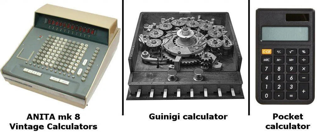
Finally, the age of digital electronics witnessed the birth of the transistor, the pinnacle of semiconductor technology, which allowed the extreme scaling down of size and made calculators cheaper and more accessible.
The Components
- Input: The components lie in a shell of robust or durable plastic with holes in it. These holes are filled by buttons composed of rubber that push through. The numbers and operational symbols are drawn on these buttons, and when pressed, they complete a circuit beneath, sending electrical impulses through a circuit board.
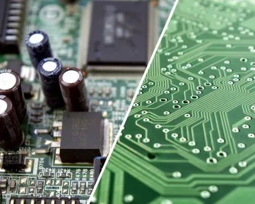
- Processor: The microprocessor is the brain of the calculator, and is an integrated chip that contains an entire Central Processing Unit (CPU) on a single silicon microchip.
- The processor identifies the pressed buttons and operates on the number’s binary values, strings of ‘1’s and ‘0’s – the only language it understands.
- The processor will store the binary inputs temporarily in its registers and perform the required operation on them. The resultant binary output is again converted to a decimal and displayed.
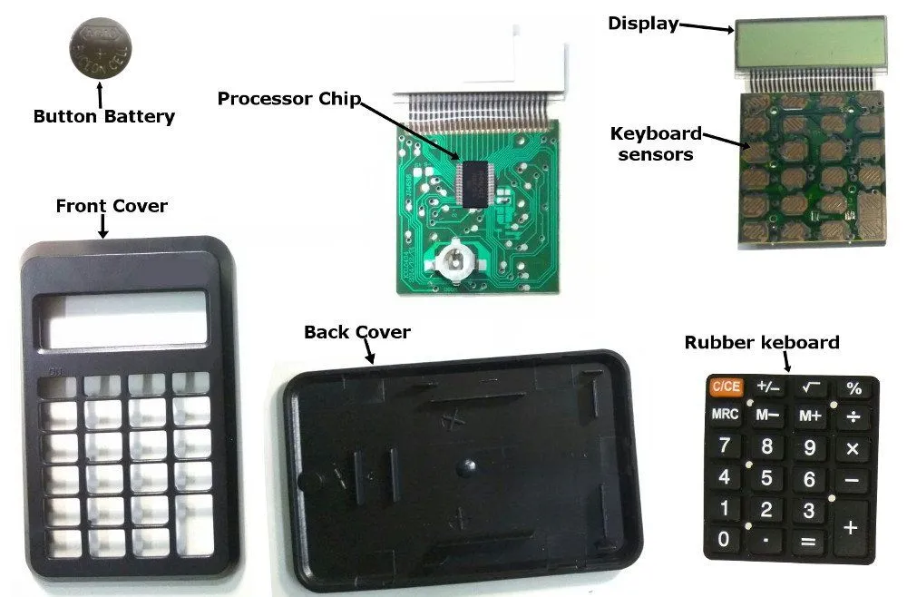
- Output: The output is displayed on an LCD (Liquid Crystal Display) screen. The display works by applying an electric field to liquid crystal molecules sandwiched between two polarizing filters, which controls whether light passes through specific segments of the screen. Earlier models used LED screens that consumed more power. The display immediately shows the input numbers as they are typed, as well as eventual result the calculator spits out.
- Power: Basic calculators are powered by small coin cell lithium batteries (such as the CR2032) or photovoltaic solar cells that convert ambient light into electrical energy. Many calculators use both, with the solar cell as the primary power source and the battery as a backup.
How Do Calculators Work?
The Basics
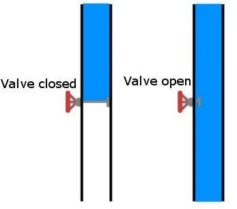
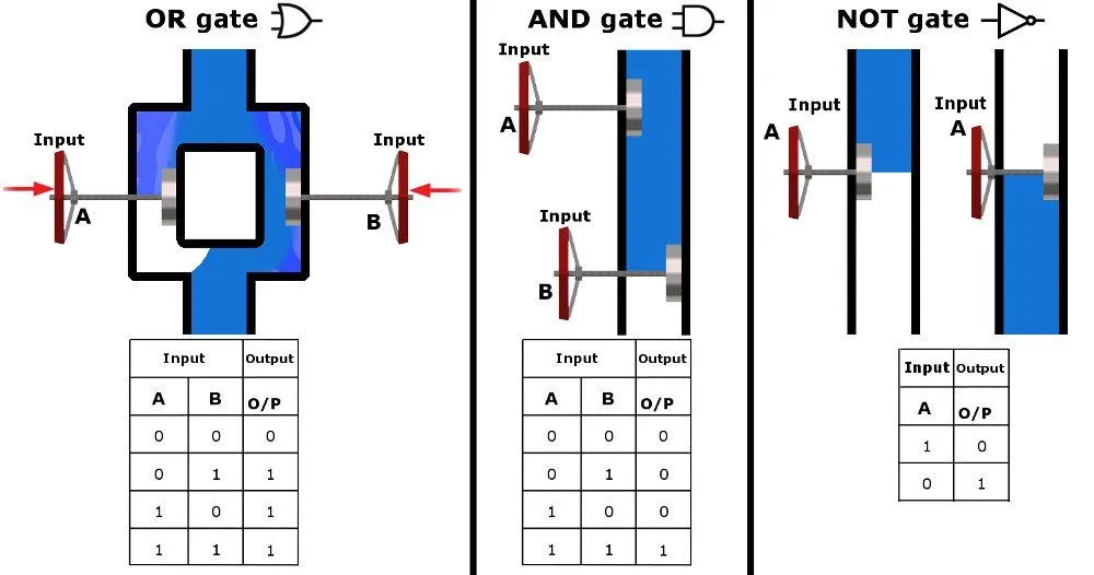
The transistors are paired in particular ways to form logic gates, which provide specific outputs according to the placement of these transistors. The most basic ones are AND, OR and NOT gates. Our analogy of transistors as taps will make our understanding of transistors and logic gates much easier. For a more detailed explanation, click here. Water that is allowed to flow with an open knob is interpreted as ‘1’ and water blocked due to a closed knob is interpreted as ‘0’.
It is informative to know that the processor does not convert a decimal number into binary bits, but rather, these numbers are drawn for our convenience only.
The processor recognizes the button or an input via the circuit path and holds its binary value. For instance, 2 is written as 10 in binary. However, it converts binary to decimal each time it has to display what you have entered or the results of an operation. Explaining the conversion of numbers to different systems is time-consuming and irrelevant right now; all you need to understand is that the processor uses circuits that convert numbers and perform operations on a train of ‘1’s and ‘0’s.
The AND gate employs transistors in a series configuration and performs logical conjunction, whereas the OR gate consists of two transistors in parallel configuration and performs logical disjunction. The NOT gate simply negates the input, i.e., converts a ‘1’ to a ‘0’ and vice versa.
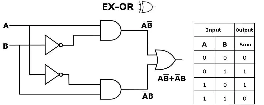
The combination of these gates can be used to form another important logic gate: Exclusive-OR gate. This gate gives the impression of adding its two inputs. The EX-OR operation is simple; it produces a ‘1’ when its inputs are different.
A calculator uses millions of such logic gates arranged in particular ways to perform complex operations on input numbers.
Let’s find out how these particularly arranged gates execute complex operations. However, our explanation is only limited to addition and multiplication to give you a general idea. Believe me, it gets much more complicated!
The Adder
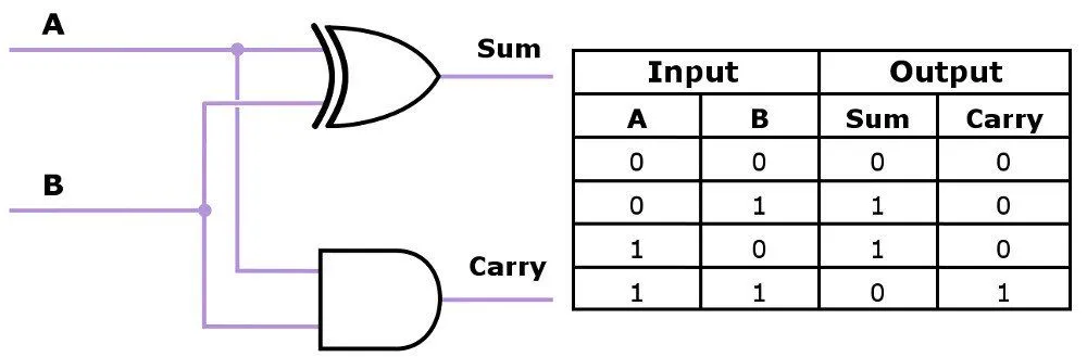
The adder is a logical circuit that adds two bits – A and B – but how is it any different from the EX-OR gate?
Looking at the final sequence of inputs for an EX-OR gate, one can see that although the sum of ‘1’ and ‘1’ is ‘0’, it also generates a carry bit that is not included in our table.
The circuit generates another bit that is “carried over” and stored as an extra bit in the memory. The bits are actually separated into two columns – sum and carry. Looking at the table, one sees that the sum can be generated by an EX-OR gate, while the carry over bits represent an AND gate. The two outputs can be generated simultaneously using a circuit known as a half adder.
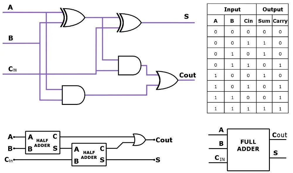
But again, the circuit does not consider any carry over bit forwarded to it by a previous adder. A three-input adder that considers the carry-overs from a previous adder is called a full adder.
Two ‘1’s generate a ‘0’ with a ‘1’ carry, and three ‘1’s generate a ‘1’ with ‘1’ as a carry too. The carry out bit is forwarded to the next adder. The full adder can be viewed as a combination of two half adders or a combination of different logic gates.
This complex circuit only adds one bit. (Yes, all that hassle for only one!)
Further, ‘n’ such bits can be added by an n-bit adder, which is a combination of ‘n’ full adders, with their carry overs passed on to the next adder. The individual sums are grouped together as the total sum, with a carry over generated by the last adder.
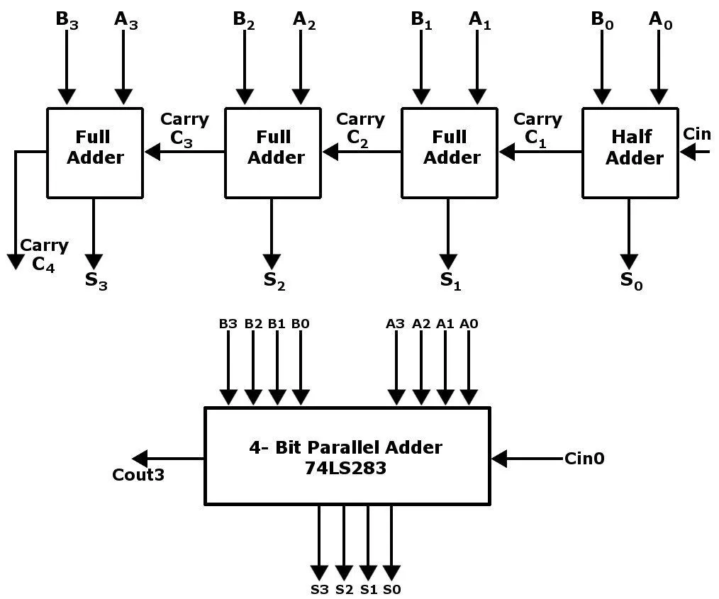
4-bit adders are combined to form 8-bit adders and so on in order to add larger numbers.
The Multiplier
The process of binary multiplication is similar to decimal multiplication, although implementing it using gates is difficult.
For instance:
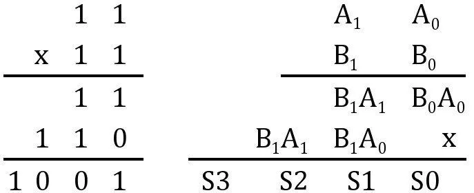
Also, the number of output bits generated are double the size of the seeded input bits. The operation can therefore be implemented by what is called partial product accumulation. The example shows the multiplication of two 2-bit numbers – A and B – which produces sums that are the products of individual bits.
The individual products are generated by 4 AND gates. Furthermore, these sums can be added with the help of half adders to produce the sums S4-S0, grouped together to form S, the product of A and B.
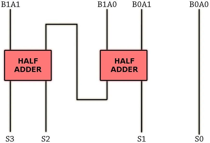
Similarly, using the same principle, 4-bit numbers can be multiplied together using 16 AND gates and 12 adders to generate an 8-bit number and so on.
The calculator also subtracts and divides numbers using similar logic gates. It is important to know that we have explained the most basic or primitive circuits to add and multiply, just to give you a general idea. These circuits were long ago replaced by much faster and quicker circuits. A computer uses the very same logic gates for general purpose computing, which is brought about by calculating and crunching numbers at its core. The calculator only calculates; it is not programmable.
As more and more transistors were stacked on a processor, the range of operations for calculators expanded. Today, calculators are far more advanced, with scientific calculators featuring more memory and superior processors. They are used by professionals, such as engineers and scientists, to perform logarithmic calculations, calculus, and even graphing. Modern graphing calculators, such as the TI-84 and Casio fx-CG50, contain processors with millions of transistors and can run programmable applications. And now, the basic calculator, like so many other devices, has been integrated into our smartphones.
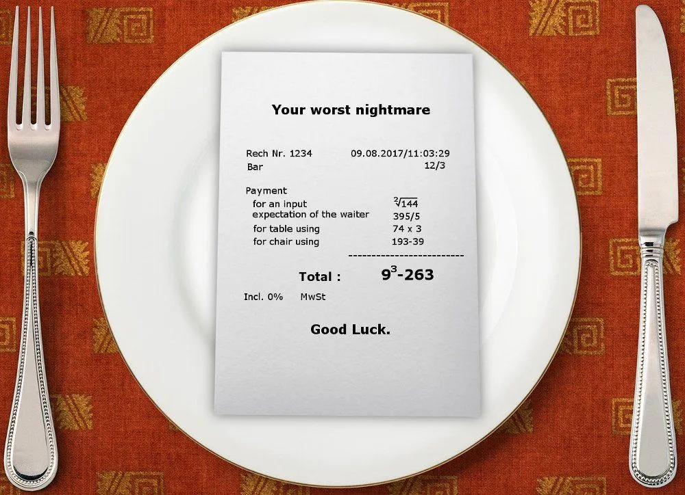
Although it has relieved us of the torments that mathematics represents for so many of us, it is believed that our dependence on such devices has made us cognitively lazy. The amount on the bill might not split into seven perfectly every time, but do it in your head once in a while just to keep the juices flowing. You never know when your phone will be dead and you’ll be forced to do dreaded math in your head – just like in the good old days!